I’ve recently decided to attempt a hand-wired keyboard out of curiosity, and because of the surprisingly simple steps, I’ve decided to make an article about it to hopefully encourage more DIY builds here :).
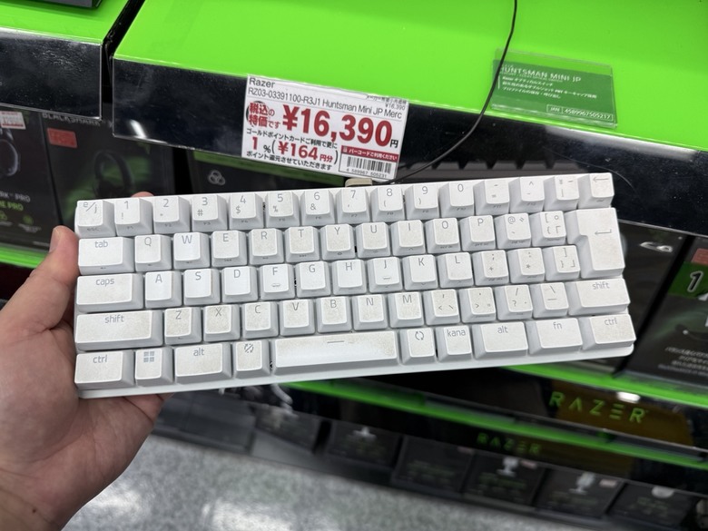
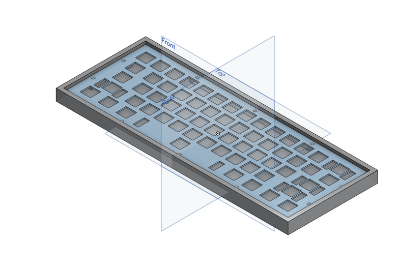
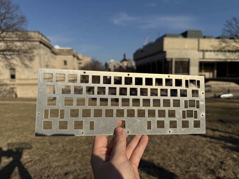
The main components of a barebones handwired keyboard are a microcontroller, switches, diodes, wires, keycaps, and a mounting plate. To begin with, I designed my mounting plate via keyboard layout editor, then I exported the 2D file into onshape. With the mounting plate successfully imported into Onshape, I’m free to design a case around the plate and check wether or not the switches I’m considering will fit (in this case I’ve went with the HMX Poros). At the time I wasn't aware, but there is a crucial flaw in this design, and its the lack of holes for the stabalizers, so if you intend to try this yourself DO NOT forget this. (cutting a small hole through metal is quite challenging with wires attached lol.)
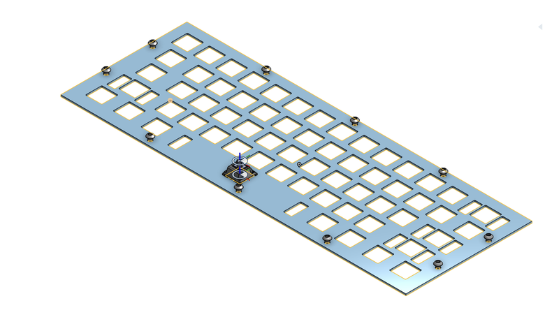
With everything ready and the dimensions of the mounting plate decided, we can begin manufacturing the mounting plate. There is many choices for this, the easiest being 3D printing the plate (preferably around 1.5-3mm thick). If you want to explore with other materials laser cutting is also an option, however, I’ve decided to use a water jet in order to have an aluminum mounting plate.
Now we put a switch in every slot, and can begin the soldering! (if you have stabalizers, this will be the time to put them in)
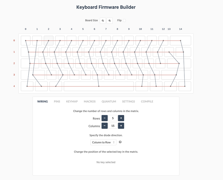
The cable formation of the keyboard is incredibly simple; all it is essentially is a matrix, and it can vary in row/columns depending on your keyboard layout. To better visualize this, you can download the raw file or JSON file of your keyboard plate directly from the keyboard layout editor or Onshape to kbfirmware. After putting down your rows/columns number, you should be able to see the generated wiring pattern.
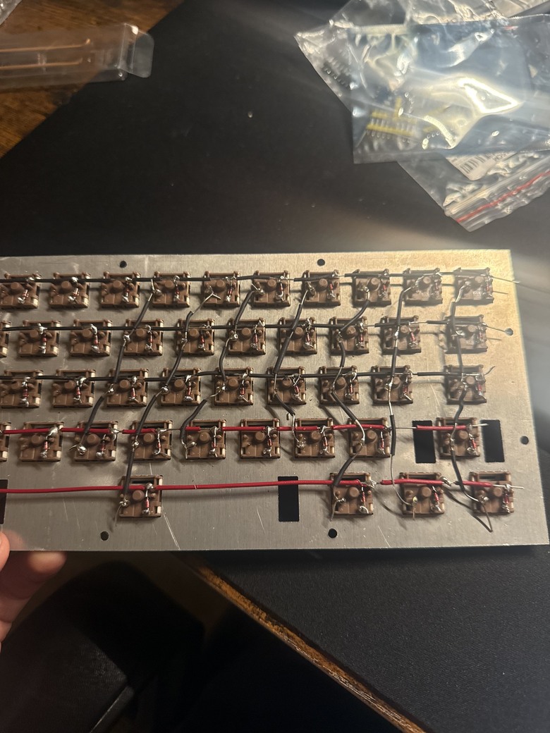
Before beginning the soldering, it is wise to prep the diodes first by bending them all 90 degrees first on the end without the black mark (in this case I’m using the 1N4148 diode), then make a small loop like this:
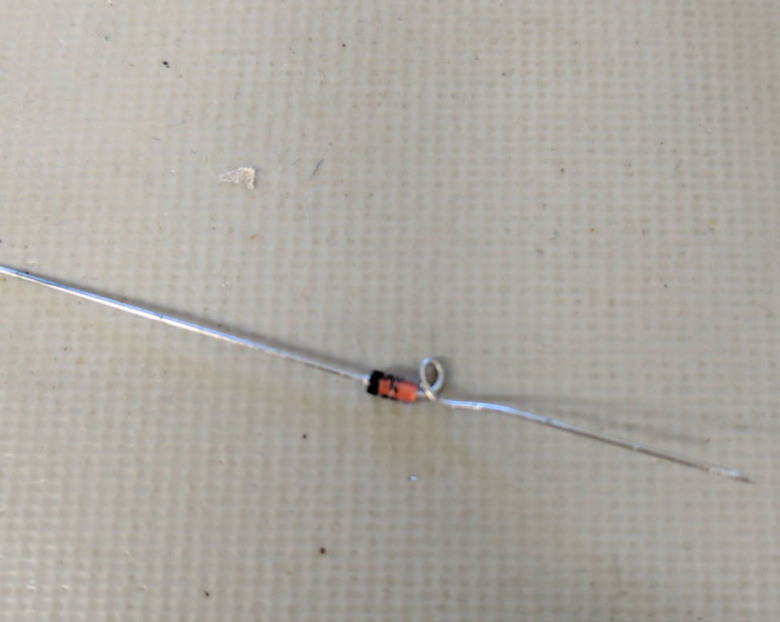
You will then put this loop on the bottom right pin of every single switch, and solder it in. (Remember to cut off the extra ends on the soldered part to keep the process as clean as possible)
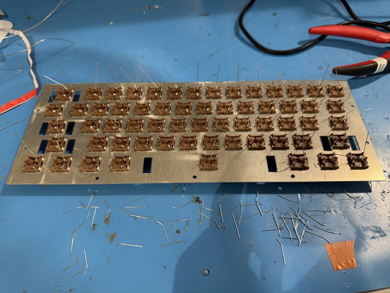
The next step would be soldering in your rows. To do this, cut a wire the length of the keyboard, giving myself some extra length in the process. Since the column wires will be overlapping row wires, a plastic/non-conductive insulation is needed; this could be done by either cutting slits in the original wires (harder) or putting on electrical tape/heat-shrink-tubing where the wires would touch (much easier). After the insulation is installed, we bend the top parts of the diode (the end with the black mark) onto the slits without insulation, then solder it in.
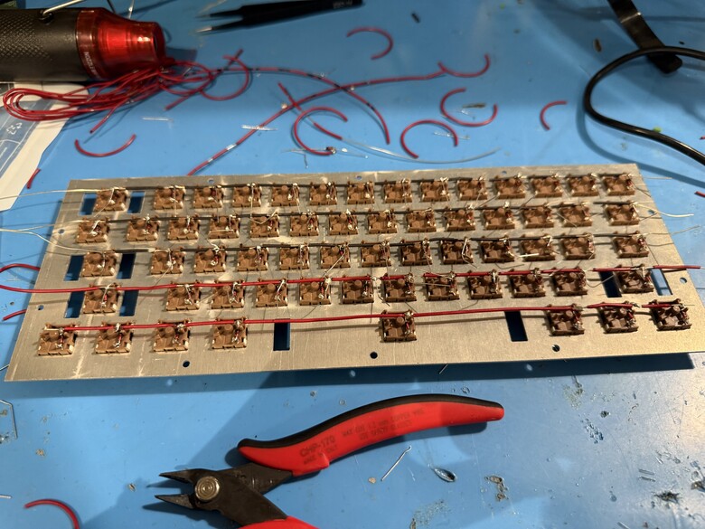
Now to do the columns, I cut wires the width of the mounting plate, and stripped it completely (of course, you can keep insulation where the wires overlap if you want to). Then I looped the wire around every left pin on the column; this step is essential; make sure to double or even triple check your connections and layouts!!!
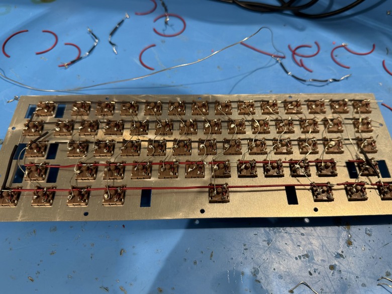
Once everything is soldered in, check your connections! Make sure every pin is soldered in and that the number of columns and rows matches what was planned.
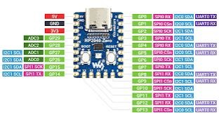
Now, for the microcontroller, I’ve decided to go with the RP2040-zero. To solder them in, all I did was measure out the wire lengths, then solder the wires into the pin slots and into each individual column/row. To help with this process, you can search up your microcontroller’s pinout diagram to know which slots are usable; this can also help with configuration later. Also, where the wire connects isn’t important as long as each column/row is connected to the microcontroller.
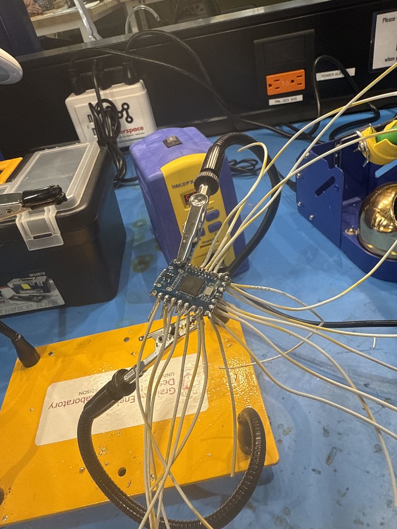

The installation of the firmware will vary depending on what type of microcontroller you decide to use. Refer to the KMK and QMK GitHub to know which firmware to use! Since my microcontroller at the time had yet to be fully integrated by QMK and KMK, I opted to use POG. Unfortunately, I do not have the keyboard on hand, nor do I have screenshots of setting up the firmware. However, the process has already been streamlined by this software, and simply following the steps instructed should prove no error!
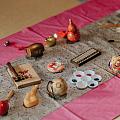
After the configuration has been done and each key has been tested, the keycaps can be installed:
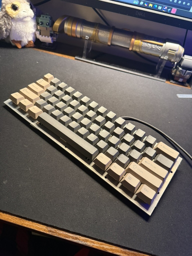
Aaaaand its practically done, which is good enough to me. There are still a lot of small issues with the keyboard, like the microcontroller also needs insulation, the lack of mounting screws for the stabalizers, and the most obvious lack of a case... However, this should be a quick and simple documentation of how to make a handwired keyboard. If there's any questions or needed clarification, feel free to leave a comment.